
GRACE-FO - Gravity Recovery and Climate Experiment-Follow-On Mission
Contact
GFZ Websites
Project Webpage
Data Access via
Infrastructure belongs to
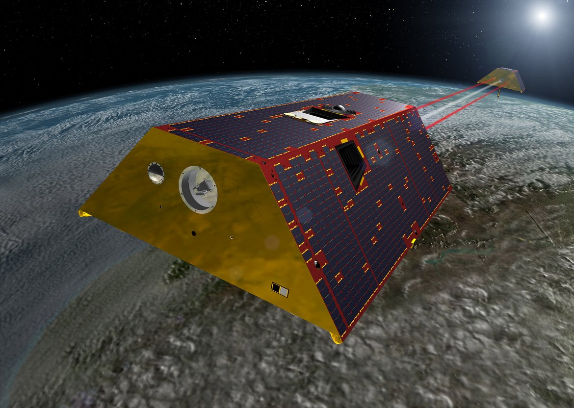
The primary objective of the GRACE-FO Mission is, as for GRACE, to obtain precise global and high-resolution models for both the static and the time variable components of the Earth's gravity field. As in the original GRACE mission, this goal is achieved by making accurate measurements of the inter-satellite range between two co-planar, low altitude and polar orbiting twin satellites using a K/Ka-Band ranging (KBR) system. Additionally, each satellite carries a geodetic quality Global PositioningSystem (GPS) receiver for precise positioning and time-tagging, a Laser Retroreflector (LRR) for independent ranging from ground, and high accuracy accelerometers to precisely measure the non-gravitational forces acting on the satellite.
As a secondary goal, GRACE-FO carries a Laser Ranging Interferometer (LRI) as a technology demonstration. The LRI provides, same as the KBR system, inter-satellite range changes, but with much higher accuracy, and demonstrates laser-ranging technology in support of future GRACE-like missions. Another secondary objective is the continuation of GRACE radio occultation measurements, such as GRACE-C or NGGM (Next Generation Gravity Mission).
The GRACE-FO project is executed in the US under the direction of the NASA Earth Science Division (ESD) within the NASA Science Mission Directorate (SMD) and the Earth Systematic Missions Program Office at Goddard Space Flight Center (GSFC). The Jet Propulsion Laboratory (JPL) is assigned responsibility for the GRACE-FO project on the US side.
The GRACE-FO mission has significant German contributions managed by GFZ. Funding of the German contributions was jointly secured by the Federal Ministry of Education and Research (BMBF), the Federal Ministry for Economic Affairs and Energy (BMWi), the Helmholtz Association (HGF), the German Aerospace Center (DLR) (LRI in kind contributions) and GFZ.
The cooperation between NASA and GFZ was defined in a Memorandum of Understnding (MOU), the roles and responsibilities are described in a Cooperative Project Plan (CPP). According to the CPP GFZ was responsible for (1) science data exploitation and dissemination within the joint US/German Science Data System (SDS) including release of product versions of the GRACE-FO science data products through their Information System and Data Center (ISDC); (2) provision of developments for the experimental Laser Ranging Interferometer (LRI); (3) provision of a Launch Vehicle and Launch Services; (4) provision of Laser Retroreflector (LRR) for each spacecraft; (5) mission operation (with US-support and subcontracted to DLR/GSOC with GFZ in-kind funding); and (6) leading the European Science Team.
GRACE-FO was successfully launched on May 22, 2018, from Vandenberg Airforce Base in California on a Space-X/Falcon-9. The GRACE-FO Mission Operations System (MOS) and Ground Data System (GDS) are funded by GFZ (for the first 5 years and now in its Extension Phase until end of 2029) and sub-contracted to DLR’s (DeutschesZentrum für Luft- und Raumfahrt) German Space Operation Center (GSOC) in Oberpfaffenhofen. GFZ provides the Operations Mission Manager (OMM), validated flight procedures and the Ny-Ålesund/Spitzbergen (NYA) ground station complex.
Categories
Disciplinary Keywords
Instrumentation
The GRACE-FO Science Instrument System (SIS) includes all elements of the inter-satellite K/Ka-Band ranging (KBR) system, the GPS receivers required for orbit determination and occultation measurements, and associated sensors, such as the star tracker assembly (STR) and the accelerometer (ACC). These elements are in general identical to GRACE, but based on up-to-date hardware and software. In addition, a Laser Ranging Interferometer (LRI) has been added to the GRACE-FO mission for the purpose of demonstrating improved inter-satellite ranging accuracy. Additionally, GFZ provided Laser Retroreflectors (LRR) for both satellites for independent orbit determination control. The SIS also coordinated the integration activities of all sensors, assuring their compatibility with each other and the satellite. In the following, the different SIS components are shortly summarized. Note that the Attitude and Orbit Control System (AOCS) sensors, which include besides the GPS Receiver Assembly a Coarse Earth Sun Sensor (CESS), an Inertial Measurement Unit (IMU) and a fluxgate magnetometer, are described in the Satellite System (SAT) page.
Instruments
-
GPS Receiver Assembly
The GPS Receiver Assembly is part of the Microwave Instrument (MWI) and tracks the GPS satellite ranging signals for (1) satellite position and clock determination for on-board operations, (2) precise absolute orbit determination and time-tagging of science data, and (3) radio occultation measurements for atmospheric studies.
It consists of the main zenith navigation antenna, the rear back-up navigation antenna and a rear occultation antenna through which the GPS signals are received. These signals are passed to the Signal Processing Unit (SPU), which receives, down-converts and digitizes the GPS signals. The sampled data are passed to the Instrument Processing Unit (IPU), which extracts and delivers the GPS phase and pseudo-range measurements. GPS data are also the basis for the determination of the satellite position and clock estimates required for on-board operations and processing of science data.
-
K/Ka-Band Ranging (KBR) Assembly
The K/Ka Band Ranging (KBR) system is another part of the MWI and provides precise (within 10 µm) measurements of the distance (and its changes) between the two satellites from which the fluctuations in gravity can be determined. It consists of a transmit/receive horn at the front plate of the satellite, a wave-guide assembly and a Microwave Assembly (MWA). A reference signal is generated by the Ultra Stable Oscillator (USO), which is then up-converted to 24 and 32 GHz bands by the MWA, and transmitted to the other GRACE-FO satellite through the wave-guide and horn. The horn and the MWA also receive and down-converts the K/Ka-Band signals from the other satellite, using the same reference K/Ka-Band carrier that was transmitted. The received signals are passed to the SPU for digitization and in turn to the IPU for digital signal processing. The SPU ensures that the KBR signals are sampled at the same epoch as the GPS tracking signals, ensuring precise time-tagging of the KBR measurements.
-
Laser Ranging Interferometer (LRI)
The LRI is a joint US/German instrument and serves as a technical demonstration to assess if precision laser interferometry can improve microwave inter-satellite ranging performance for future GRACE-like geodetic missions such as GRACE-C. Inter-satellite ranging sensitivity is one of the factors that determine the overall performance of GRACE-FO. Further details are provided at the Max Planck Institute for Gravitational Physics (Albert Einstein Institute, AEI) in Hannover.
-
Laser Retro-Reflector (LRR)
The passive Laser Retroreflector (LRR) was contributed by GFZ and provides distance measurements of the GRACE-FO satellite orbits relative to the terrestrial ILRS tracking network. Four corner cubes are mounted on the nadir surface of the satellite, which reflect laser-ranging signals transmitted from the ground. The operating characteristics for the LRR are determined by the ILRS ground segment.
-
Microwave Instrument (MWI)
The GRACE-FO Microwave Instrument (MWI) consists of the GNSS receiver and the K-band ranging (KBR) assembly.
-
SuperSTAR Accelerometer (ACC)
The SuperSTAR Accelerometer measures the non-gravitational accelerations acting on the satellite. These accelerations include air drag, solar radiation pressure, Earth radiation forces, thermal forces and forces created by operating the attitude control activators. The measurements are used to model the evolution of the satellite orbits due to the non-gravitational forces, so that the contributions to the inter-satellite range changes due to purely gravitational effects can be correctly discriminated. Accelerometer measurements may also be used, in conjunction with other data and models, to determine upper atmospheric density variations.
Links
GFZ Websites
Project Webpage
Data Access via
Relationships
- is related to
- AOD1B - GRACE Atmosphere and Ocean De-Aliasing Level 1B Product
- ESA ESM - the updated ESA Earth System Model for Gravity Mission Simulation Studies
- GFZ Data Services
- GRACE - Gravity Recovery and Climate Experiment
- GRACE-C - Gravity Recovery and Climate Experiment Continuation Mission
- Globalwaterstorage Information Portal
- GravIS - Gravity Information Service
- ISDC - Information System and Data Center
- Magnetic Satellite Data Products
- Satellite Receiving Station Ny-Ålesund (Spitsbergen)